Rendeer is a rasterizer I developed in 2019 on a quest to learn how 3D rendering works.
Features#
- Imports a mesh in Wavefront .obj format
- Can render the mesh with flat shading, Gouraud shading, or as a wireframe
- Allows you to animate the mesh and render out the frames.
Development#
The first step towards rasterization was projecting the 3D vertices of a model onto a 2D plane called the screen space.
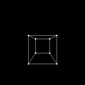
Figure 1. Projection of a cube from the front.
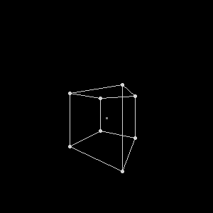
Figure 2. Same cube viewed from an angle.
To reduce unnecessary computation later on, I applied a process known as back-face culling to discard all triangles facing away from the camera, as they are normally not visible. This is achieved by taking the dot product between the surface normal of each triangle and the camera-to-triangle vector, as described here in detail.
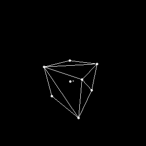
Figure 3. Triangulated wireframe cube with back-face culling.
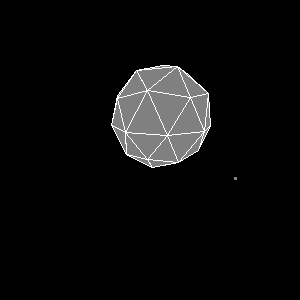
Figure 4. Solid icosphere.
For illumination I used a simple directional light source, which looks natural on small models and is straightforward to implement. The color of any surface is thus given by the angle between the surface normal and the (fixed) direction of the light, as illustrated in Figure 5.
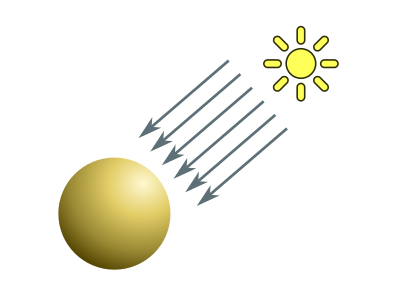
Figure 5. Directional light cast on a sphere. Areas facing the direction of the light are better lit than others.
With this addition, the true depth of the icosphere model immediately became apparent.
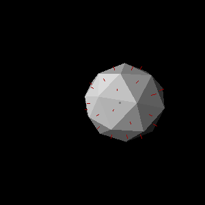
Figure 6. Let there be light! Face normals visible to the naked eye.
It was time to bring other objects into the spotlight, so I wrote a tool to read arbitrary models from .obj files. The Wavefront format is very simple. Snippet 1 displays an excerpt from an .obj defining a cube.
v 0.000000 2.000000 2.000000
v 0.000000 0.000000 2.000000
v 2.000000 0.000000 2.000000
(...)
f 1 2 3 4
f 8 7 6 5
f 4 3 7 8
(...)
Lines starting with v define a vertex and specify its coordinates, while those starting with f designate the vertices that make up a face. These two elements were sufficient for my purpose, although the format allows plenty of additional properties.
Figure 7 shows two models imported with this tool and rendered in different colors.
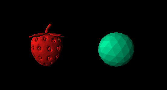
Figure 7. A strawberry (left) and a higher-face count icosphere (right).
As you can see, each triangle is filled with a single color. This technique is known as flat shading, and it does depict the geometry of the model accurately, but for smooth surfaces it is unacceptable. So I went on to implement Gouraud shading, which involves computing the light intensity for each polygon vertex based on its normal and then interpolating vertex intensities bilinearly over each polygon's surface.
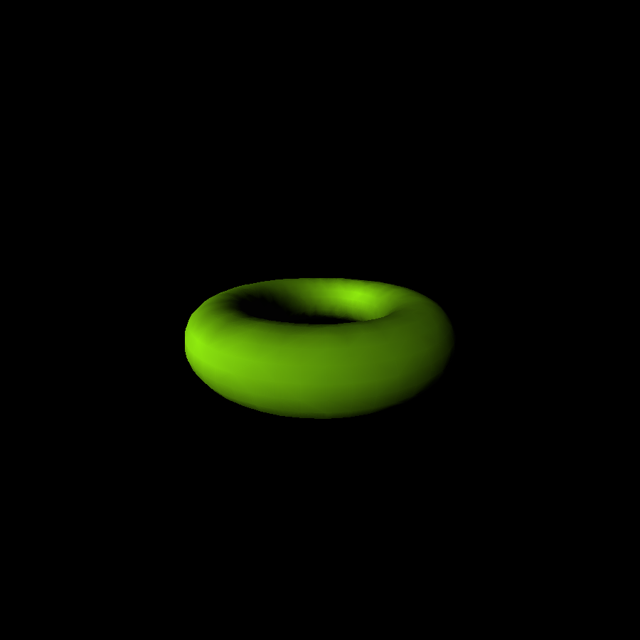
Figure 8. Smooth torus (Gouraud shading).
Once basic rendering capabilities were done, I created a regular language – and thoroughly documented it here – for describing animations to be rendered. With this new feature I could now create mind-boggling effects like the ones below.
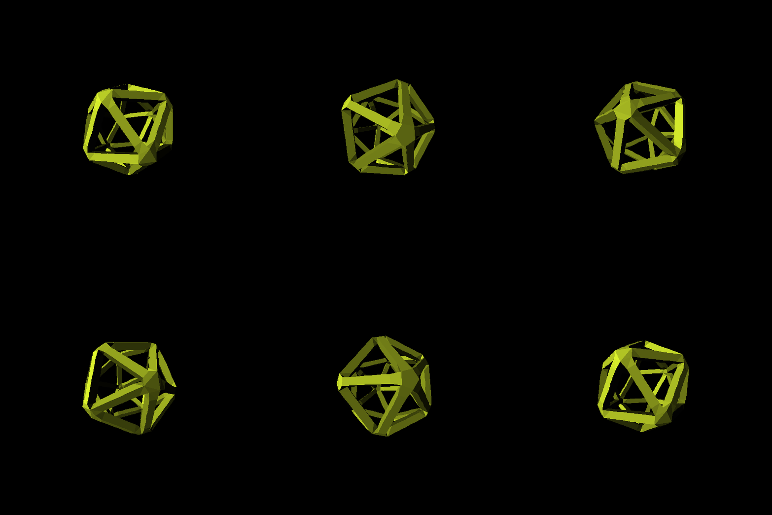
Figure 9. Abstract entity spinning.
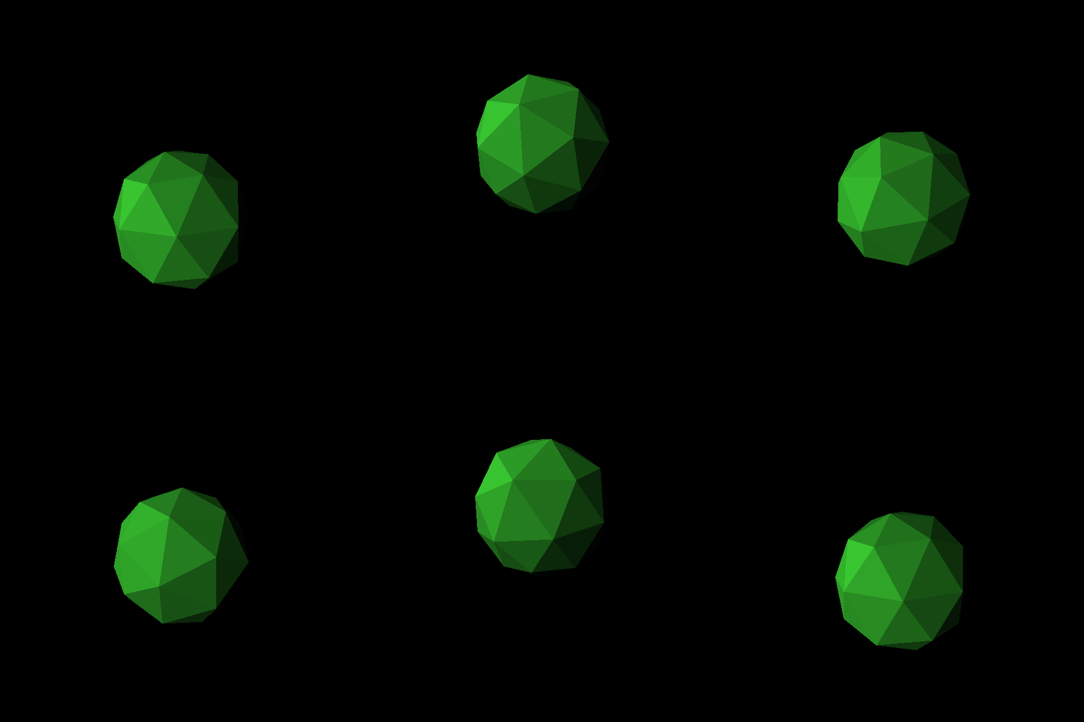
Figure 10. Icosphere in motion.
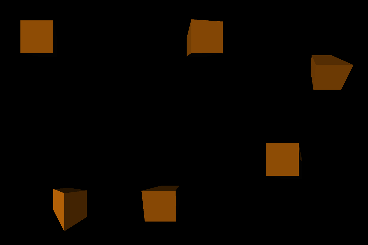
Figure 11. Cube wandering about.
Future directions#
In 2020 I set 3D rendering aside and moved on to study other topics in computer science, so I have not developed this project since. Here are a couple more features I worked on, although they never saw the light of a stable release.
Complex scenes#
Most 3D scenes worth rendering contain a wealth of objects. For this reason, I made it possible to import multiple meshes with different properties into the same scene as an experiment. Sadly, this required significant changes in architecture and the resulting code was way too messy to publish.
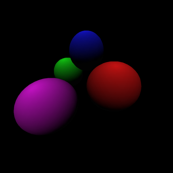
Figure 12. Many spheres going against one another.
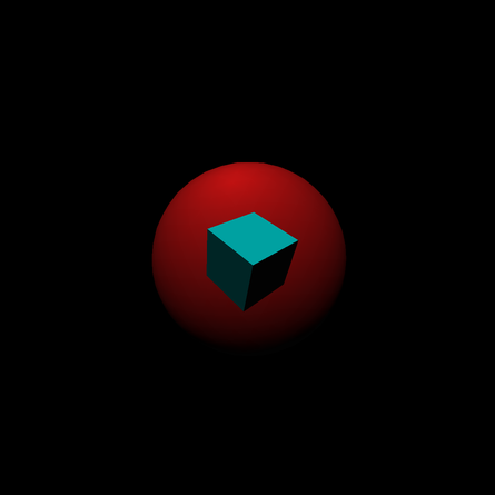
Figure 13. Cube and sphere.
Depth of field#
I achieved depth of field blur by simply rendering a depth map of the scene and using it to interpolate between the original render and a blurred version thereof – a somewhat clever trick that's unfortunately not very convincing up close.
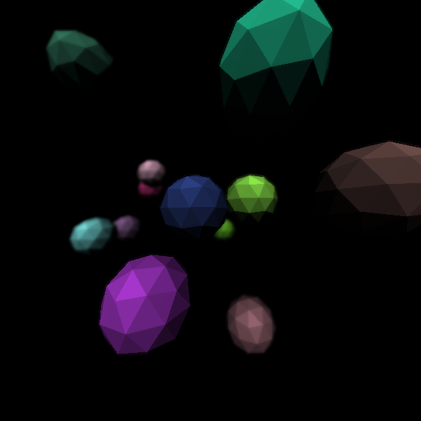
Figure 14. Narrow depth of field on a swarm of icospheres.
Lighting improvements#
Handling multiple sources of light is tricky when no ray tracing technique is used, so a single render came out remotely believable with naïve color averaging before I abandoned this idea.
I attempted to add specular highlights as well, but this came to nothing because Gouraud shading ruined the effect.
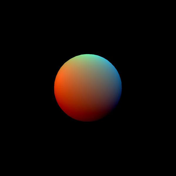
Figure 15. Multiple directional lights being cast on a sphere.
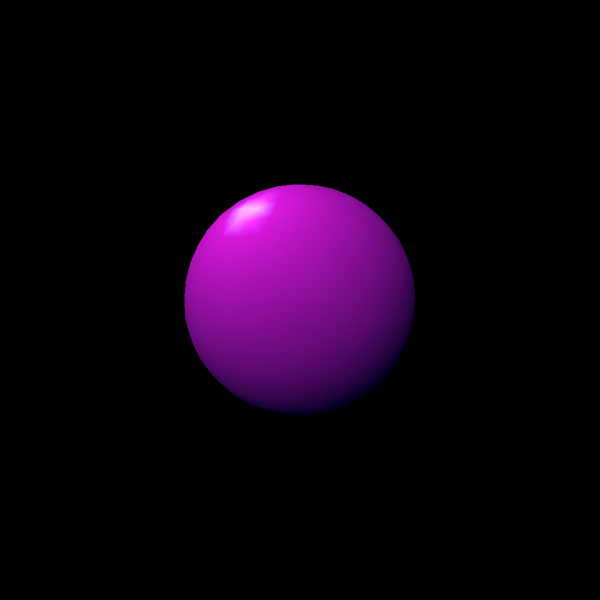
Figure 16. Specular highlight fail.
3D Graphing#
I also made it possible to plot the graph of a real-valued function of coordinates. This one turned out well, but it was too simplistic to be useful.
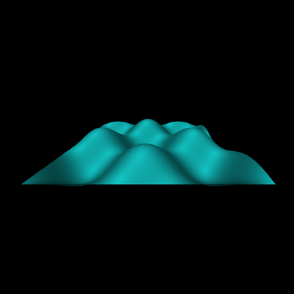
Figure 17. Wavy plot of .
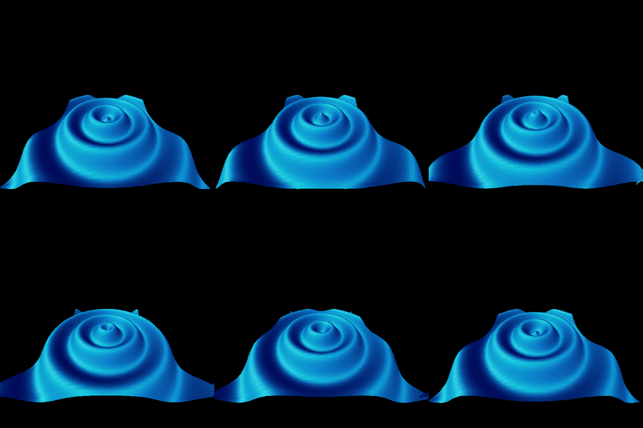
Figure 18. Sine of (distance from center plus time) with bonus glitch in the bottom right corner.
Conclusion#
The rippling surface in Figure 18 was the culmination of my efforts to create something pretty with Rendeer. Once that animation completed rendering, it was time to take a break and work on something else.
Writing a renderer was highly instructive for me and I encourage everyone to try someday. Consider checking out a tutorial on rasterizers, like tinyrenderer, or one about ray tracers, which are more visually accurate (and more exciting). Shirley, Black, and Hollasch's Ray Tracing in One Weekend in particular is a great resource.
Share this

